


Why Non-Isolated Driver Schemes MUST NOT Power Up BEFORE Load Connection
Key Finding:
Due to the inherent lack of safety features in its circuit topology, the non-isolated driver scheme absolutely MUST NOT have the input power connected BEFORE the luminaire body (LED light source). The sequence MUST be strictly adhered to: FIRST connect the luminaire load, THEN power on the driver. Violating this sequence makes instantaneous damage to the LED beads ("dead LEDs") highly probable, representing a common source of customer complaints.
Detailed Points Below:
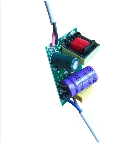
The Nature and Safety Risks of Non-Isolated Drivers:
Lack of Electrical Isolation: The defining characteristic of a non-isolated driver scheme is the absence of any safety-isolation transformer or opto-isolator providing electrical separation between the input AC line (high-voltage side) and the output DC circuit (low-voltage side, driving the LEDs directly).
Shared Reference Point for HV/LV Circuits: This means the input Line (L), Neutral (N), and sometimes Earth (Ground, G) are not fully electrically independent from the output DC +ve and -ve terminals in certain topologies. They typically share the same reference ground potential point (often the input N line or the rectified DC negative rail).
Critical Protective Components Lacking:
Missing Output Voltage Clamping: When the load is disconnected (open circuit), if the driver is powered first, the driver IC or its switch controller (e.g., MOSFET) charges the internal high-voltage bus capacitor close to the peak DC voltage of the rectified input (e.g., ~310V DC for 220V AC RMS).
Missing Effective Suppression Circuits: To simplify the circuit and reduce cost, non-isolated drivers typically omit crucial output transient voltage suppressors (like TVS diodes, MOV varistors) or soft-start/surge current limiting circuits. These components are standard or far more common in the secondary side of isolated drivers, serving to absorb switching spikes or connection transients.
Mechanism of LED Bead Damage ("Dead LEDs") from "Power First, Connect Load Later" (The Primary Culprit):
High Open-Circuit Voltage Buildup: When a non-isolated driver is powered with its output open (luminaire disconnected), its output high-voltage DC bus capacitor charges near the peak input DC voltage (e.g., ~310V).
Massive Voltage Spike & Surge Current at Connection Instant: The moment the open output (~310V) is suddenly connected to the luminaire (LED beads):
Mismatched Voltage "Shock": The typical operating voltage of the LED string is usually far lower than this open-circuit DC HV (e.g., 20V-200V depending on the number of LEDs in series). Upon connection, the high-voltage energy stored on the capacitor discharges rapidly through the wiring and LEDs.
Capacitor Discharge Creates Huge Surge Current: This discharge results in an immense surge current, vastly exceeding the rated steady-state current of the LEDs and driver. This instantaneous shock originates primarily from the capacitor discharge itself and potential overshoot generated by the driver IC reacting to the sudden load change.
Output Filter Capacitance Amplifies Impact: Output filter capacitors (or the bus capacitor contributing to output) are common in non-isolated drivers. Upon load connection, if the driver IC fails to regulate instantly, this capacitor's voltage is dumped onto the LEDs, delivering a high-voltage shock far exceeding their rating.
Parasitic Inductance Induces Voltage Spikes: Connecting wires have inherent parasitic inductance. During the rapid discharge of the HV capacitor into the low-impedance LED load, the fast current change (high di/dt) generates a voltage spike (back-EMF) via V = L * di/dt across this inductance. This spike can add significantly to the applied voltage.
LED Fragility:
Overvoltage Breakdown: A high voltage spike (significantly exceeding the LED's forward/reverse breakdown voltage) can instantly rupture the LED chip's PN junction, causing permanent open-circuit failure ("dead" LED).
Overcurrent Melting/Fusing: An enormous surge current (multiple or tens of times the LED's rated current) causes instantaneous overheating and fusing/melting of the PN junction (thermal failure) or destruction of bond wires/pads (mechanical/electrical failure).
Summary of Damage Process: Open-circuit HV -> Connection High Voltage + Huge Surge Current + Parasitic Spike + Missing Protection -> Exceeds LED Tolerances -> LED Bead Destruction.
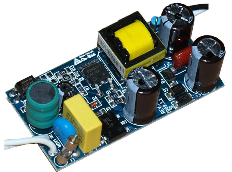
The Safety of Isolated Driver Schemes:
Inherent Isolation: The core of an isolated driver scheme (e.g., flyback) is the safety-isolation transformer. Input (primary) and output (secondary) circuits are physically and electrically isolated. Energy transfer occurs solely via magnetic coupling; no direct electrical connection path exists.
Complete Protective Measures:
Open-Load Protection/Clamping: Detects high output voltage under no-load and stops switching/limits output voltage to prevent uncontrolled secondary voltage rise.
Overvoltage Protection (OVP): Shuts down output on abnormal voltage increase.
Isolated Secondary Feedback: Output voltage/current feedback is typically sent to the primary side via an opto-coupler, maintaining electrical isolation. The secondary itself employs voltage and current feedback loops.
Integrated Protection: Driver ICs and peripheral circuits usually incorporate:
Secondary-Side Protection Devices: Easier implementation of TVS, MOV, etc., directly on the secondary to absorb spikes.
Soft-Start Mechanism: Many isolated driver ICs feature soft-start, gradually ramping up the output voltage during startup to effectively suppress inrush currents.
Flexible Connection Sequence: Due to inherent isolation and comprehensive protection, the secondary voltage of an isolated driver is safely clamped when powered without a load (typically very near the operating voltage). Therefore, powering the driver before connecting the load, or making connections cold before powering on, does not produce the destructive overvoltage/overcurrent transients. This is why safety standards (e.g., UL, IEC) demand isolated drivers pass rigorous open-output, overload, etc., testing.
Installation Practice & Root of Complaints:
Hazardous Installation Habits: As noted, electricians at construction sites often habitually connect the driver to AC power first for testing or convenience, then probe the output with a meter or connect the luminaire wiring live.
Lack of Awareness/Ignorance of Special Requirements: Installers may be unaware of the specific safety sequence required for non-isolated drivers (load MUST be connected BEFORE power), or, even if aware, may neglect it due to oversight or time pressure.
Batch Failure & Early Mortality: One improper installation act can instantly destroy an entire LED strip (or large segments), rendering the luminaire completely inoperative ("dead") or partially non-functional. This immediate, physical damage is a classic early failure mode and a direct source of customer complaints, severely undermining perceived product quality (even when the root cause is installation error).
Regional Variations: While non-isolated drivers can be reliable in regions with stable electrical environments (low voltage fluctuation), the risk introduced by human installation habits remains. Therefore, isolated drivers are the safer choice, especially in regions with strict regulations or where standardized installation supervision is difficult.
Summary & Recommendations:
Enforce Installation Procedure: Manufacturers MUST prominently emphasize, in manuals, driver labels, and guides: "WARNING: Connect Luminaire Load BEFORE Applying Power! Operation without load WILL damage the fixture."
Prioritize Isolated Drivers: Especially for engineered/commercial luminaires, high-value fixtures, scenarios with difficult installation control, or high customer service demands, strongly prefer isolated drivers. They tolerate improper sequencing, drastically reducing failure rates and complaints.
Intensify Installer Training: Distributors and end customers MUST be clearly informed about the specific operating requirements of non-isolated drivers to avoid losses and liability disputes. For consumer products, isolated drivers are strongly recommended.
Limitations of Non-Isolated Schemes: While non-isolated drivers offer advantages (cost, efficiency, size), their use MUST be strictly limited to applications where the "load before power" sequence is guaranteed (e.g., factory-assembled, driver/luminaire integrated units, highly automated installation).
In Brief: Non-isolated drivers have output terminals inherently referenced to dangerous HV. Lacking protection circuits, they store high voltage/energy when powered open-circuit. Connecting the load releases this energy onto the vulnerable LEDs as massive voltage spikes and surge currents, causing irreversible damage. Isolated drivers, through inherent isolation and multi-layered protection, effectively avoid this risk. The critical trigger is installer habit; managing this human factor is key to preventing complaints.