Why Achieving Flicker-Free Performance is More Challenging with PF0.9 LED Fixtures vs. PF0.5
Core Reason:
High-power-factor (PF) circuits exhibit larger output bus voltage ripple, and suppressing this ripple entails greater technical difficulty and cost.
Differences in Input Current Waveform & Rectified Pulsing Patterns
🔹 PF0.5 (Low PF):
Commonly employs non-isolated buck or valley-fill circuits. Post-rectification, current conducts near the AC voltage peak, generating narrow, pulsed waveforms. The filter capacitor charges primarily around voltage peaks and discharges during intervals to power LEDs. Though inefficient (low PF), this mode allows extended capacitor charge/discharge time over half the cycle.
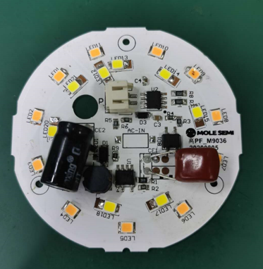
🔹 PF0.9–0.99 (High PF):
Requires active PFC (typically Boost PFC topology). The PFC controller forces sinusoidal input current that aligns with voltage phase using switching techniques. This ensures near-continuous current flow across the AC cycle, yielding smoother rectified current.
Output Bus Voltage Ripple Differences
🔹 PF0.5:
Rectification produces high-peak pulsating DC (full-wave), but the filter capacitor charges close to AC peak voltage (e.g., 320V at 230V input). This lower voltage permits large-capacity, high-voltage-margin electrolytic capacitors without significant size/cost penalties. The large capacitance absorbs ripple effectively, keeping bus ripple valley above LED operating voltage. Downstream constant-current (CC) circuits thus operate stably, enabling flicker-free output.
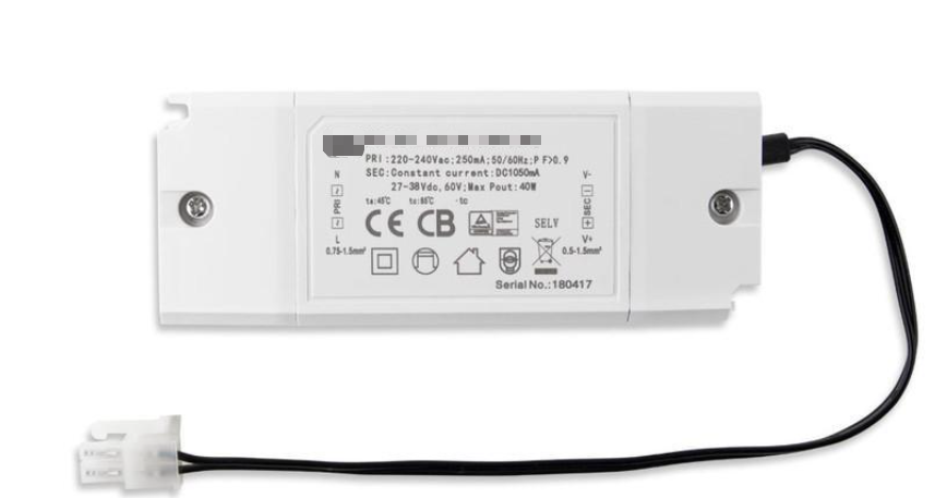
🔹 PF0.9 (Boost PFC):
High Bus Voltage: PFC output is typically set to a high, stable DC level (e.g., 390–400V) for wide input range and efficiency.
100Hz Ripple Inevitability: Boost PFC prioritizes current shaping, not voltage regulation. Its output unavoidably carries large 100Hz ripple (double line frequency), especially at light loads.
Capacitor Energy Limitation:
Filter capacitors operate at higher voltages (400V vs. 320V), drastically reducing capacitance and energy storage (E=½CV²) within similar size/cost constraints. Example: A 400V/100μF capacitor stores less energy than a 320V/220μF counterpart. With ripple ΔV = (I · Δt)/C, high-voltage capacitors fail to absorb sufficient ripple energy, leading to large Vpp (e.g., 40–50V at 40W load).
Ripple Impact on Constant-Current Control (Flicker Mechanism)
Flicker-free operation demands uninterrupted LED current throughout the AC cycle.
🔹 Dilemma for PF0.9 Circuits:
Excessive Ripple: Bus ripple amplitude is large (e.g., 40–50V).
Minimal LED Voltage Margin: LED string voltage (e.g., 350V) approaches the ripple valley (e.g., 380V).
CC Control Failure: When the bus valley nears or drops below the LED’s minimum forward voltage (VFmin), CC controllers (buck/linear ICs) lack sufficient headroom. Near the valley, MOSFETs enter linear mode or cut off, causing LED current dropout and severe flicker.
Overcoming High-PF Ripple for Flicker-Free: Key Challenges
1. Two-Stage Driver Design
Principle: Add an isolated DC-DC stage (e.g., Flyback, LLC) after PFC to buffer ripple and stabilize voltage for the CC stage.
Pros: Most reliable solution for flicker-free performance.
Cons: Higher cost/bulk, reduced efficiency (multi-stage conversion).
2. High-Voltage Film/Hybrid Filtering
Principle: Parallel high-voltage film capacitors (low ESR, ideal for 100Hz ripple) with PFC output.
Pros: Moderate ripple suppression.
Cons: Bulky, costly; impractical for significant ripple reduction (<20V).
3. Active Ripple Cancellation (ARC)
Principle: Auxiliary switching circuits inject/absorb counteractive current to neutralize ripple.
Pros: High efficiency, effective suppression.
Cons: High complexity/cost; limited to premium applications.
4. Advanced Valley-Fill Passive PFC + CC (Alternative)
Principle: Optimized valley-fill circuits achieve PF≈0.9 with lower output pulsation.
Pros: Lower cost than two-stage; better voltage stability vs. Boost PFC.
Cons: PF slightly below 0.95; power limit (<100W); stringent component tolerance.
Conclusion
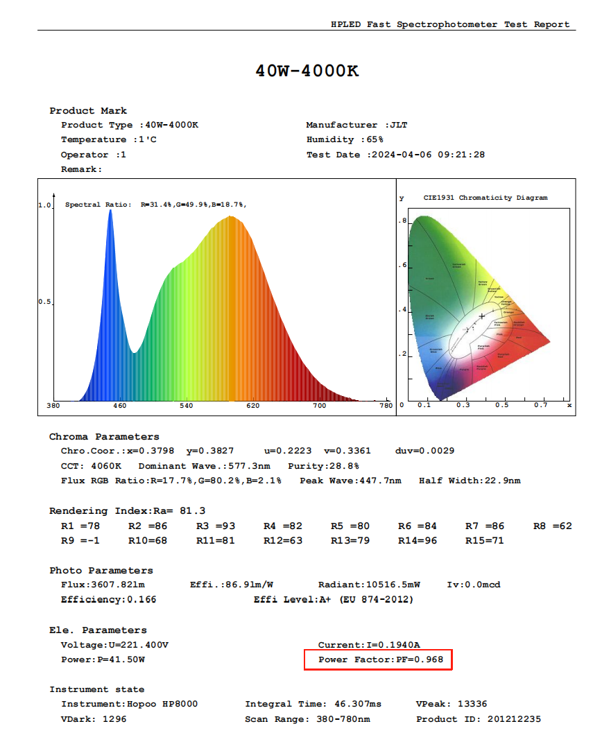
Boost PFC circuits (PF0.9) inherently produce large 100Hz bus ripple to achieve high power factor. High operating voltages limit capacitor energy storage, making ripple suppression costly. When ripple valleys approach LED operating voltage, CC circuits lose critical headroom, causing current fluctuations and flicker.
Overcoming this requires expensive two-stage designs or optimized valley-fill topologies. Simply enlarging high-voltage capacitors is cost-prohibitive and ineffective—explaining why flicker-free performance at PF0.9 is dramatically harder and more expensive than at PF0.5.
